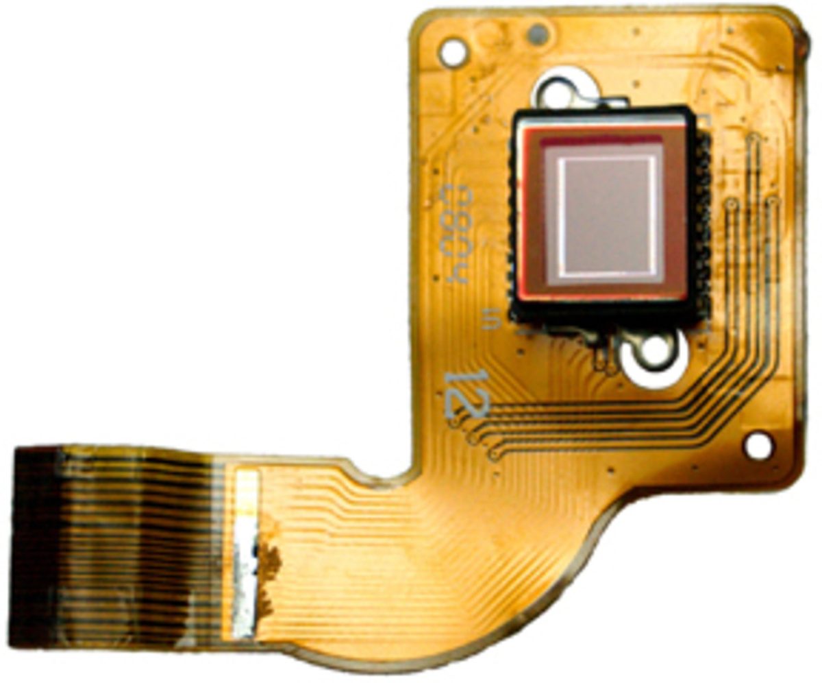
We are increasingly asked about die bonding to flexible printed circuits such as chip-on-flex and flex-on-glass. Most of these inquiries come from medical companies or bio-medical researchers exploring creative ways to bond bare die to flex circuits.
They are looking for flexible (no pun intended!) methods to use in the assembly of their products which often incorporate high density packages and the need to physically bend due to space constraints and design.
If you’ve even had the pleasure of an MRI procedure, think about the circular contraption your body goes inside. Or the space limitations of today’s super small hearing aids. Behind the scenes, there are very complex electronics using flex circuits.
SMT devices such as BGAs, QFNs, and passive devices (0402, 0201, 01005) are common in flex circuit layouts. This technology has been around for decades and is common in production cells. Chip-on-flex however proves to have significant roadblocks.
Die bonding in the traditional sense consists of Thermo-Compression Bonding of Au pads to Au bumps with a bonding temperature of 300°C. When attempting to bond die to flex at these temperatures, the glass transition (Tg) point of the flex has been exceeded and the flex becomes vulnerable to catastrophic failure. Finetech has been asked about other methods of chip-to-flex bonding, such as the use of ultrasonic and thermosonic energy and/or conductive epoxies (silver or gold filled epoxy).
The latter works! Conductive epoxies will allow an electrical conduit from the chip to the flex. But these types of epoxies have been known to lose their electrical conductive properties over time. Additionally, the high cost of epoxies with Silver or Gold is hard to justify for volume production.
Thermosonic bonding “could” be a solution – low temperature (150C) so there are no issues with Tg being pushed to the limits. Unfortunately, in order for an ultrasonic process to work, the substrate needs to be rigid. Flex circuits are organic materials and are simply not robust enough to withstand ultrasonic energy. I recently visited a customer wanting to try this process. Our bonder was able to produce 20W of ultrasonic energy for 4 seconds. All of the ultrasonic energy was absorbed into the flex because it was not rigid and, therefore, the substrate absorbed 100% of the energy of the ultrasonic transducer. Not one of the 60 bumps attached.
The most popular and successful method of chip-to-flex bonding uses anisotropic conductive film (ACF) or anisotropic conductive paste (ACP). There are subtle differences between the two, each having advantages and disadvantages. For high frequency devices, however, these normally are not a viable option. Please refer to blog #4 to understand this process in more detail.
We understand bonding. And assembly to flex circuits. Having issues or curious about how to this works? Give us a call – we’re happy to share what we know.
11/19/2015, created by: Robert Avila

